The office line standard
The line standard decides how every building element is drawn: which line type and which width a wall's cut edge, a door leaf or a stair above the cutting plane gets, on screen and on paper. The office keeps one, under Library, tab Standards, so that all its projects draw the same way. Each project is pinned to a published version and changes only when its lead upgrades it.
Line styles
A line style is a name with:
- a Line type to ISO 128-2 (continuous, dashed, long-dashed dotted …),
- a Width to 1:100, used at 1:100 and smaller scales, and a Width from 1:50, used at larger ones, both from the ISO 128 series (0.13 to 2.0 mm),
- a Colour, for the screen only: prints are always black on white.
Beside each style a preview shows it at 1:200, 1:100, 1:50 and 1:20, about twice its size on paper, so styles can be compared at a glance. It follows an edit before it is saved.
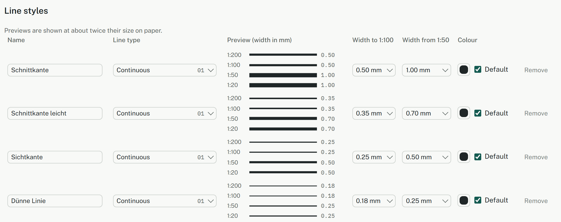
Layers can use a named style too. Free lines, polylines and arcs draw in their layer's style; building elements take theirs from the rules below.
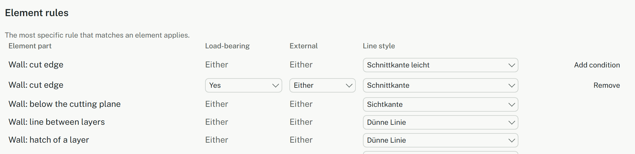
Element rules
Each part of an element gets a line style: Wall: cut edge, Door: leaf, Window: frame, Stair: above the cutting plane and so on. Every part has a rule that always applies. A wall's cut edge can have more: Add condition makes a rule for walls that are load-bearing, external or both (Either where it doesn't matter). The most specific rule that matches an element applies.
The five Pen rules (cut edges, visible edges, thin lines, hidden edges, centre lines) style the lines of placed parts and the lines drawn in sections and details, which are drawn by pen rather than by layer.
Changing and publishing
Only owners and admins change the line standard; everyone else in the office sees it read-only. They work on a draft:
- On Library, tab Standards, change styles and rules in Line standard, then choose Save draft. Discard changes goes back to the saved draft.
- Under Changes since version … the draft's differences from the latest version are listed in words. Write a Note for this version, saying why.
- Choose Publish as version ….

A published version never changes. The Version history lists every version with its date, who published it, its note and how many projects use it; View shows its styles, rules and previews and what it changed from the one before.
A project's version
- A new project starts on the version chosen under Line standard version in the New project form; the latest is preselected.
- The version holds for the whole project, every model and branch alike. A change to the office standard never restyles a running project by itself.
- A project can't deviate: it takes its version as it is and has no styles or rules of its own.
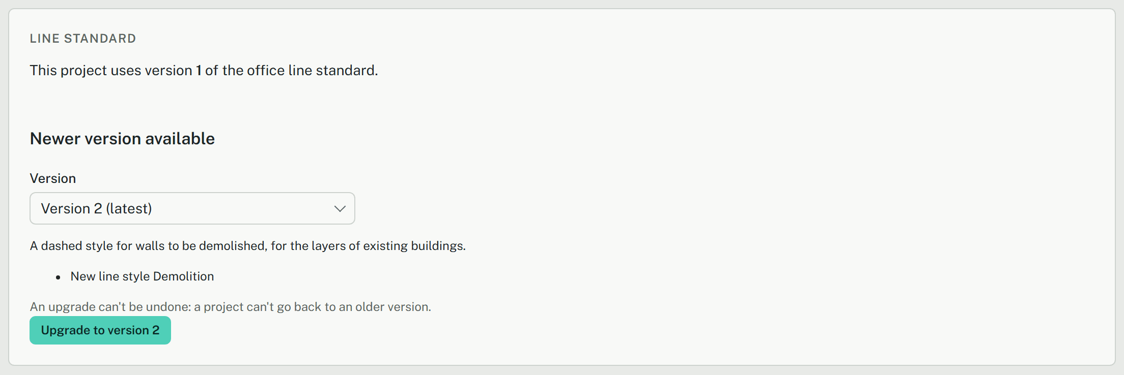
When a newer version exists, the project's settings say so under Line standard: Newer version available, with the version to look at and its changes in words. The project lead chooses Upgrade to version …. There is no way back to an older version. Each upgrade is listed under Upgrades with its date and who made it.
The editor keeps a copy of the project's version, so plans draw the same without a connection.
On screen and on paper
On paper the widths are those of the print scale. On screen they follow Lines on the plan, a scale only you see; Widths in the status bar switches to thin lines everywhere for a dense plan.
Exceptions on single elements
Now and then one element needs another line, such as a low garden wall that should read as a visible edge rather than a cut one. That is an exception, and it needs a reason:
- Select the element and choose Line style exception… under Selection.
- Choose a Line style of the project's version and type the Reason.
- Choose Set exception.
An exception is marked with a ◇ on screen, never on paper. The side panel lists those on the storey under Line style exceptions, with the line style and the reason; a click on one selects its element. Back to the standard under Selection removes it. Both are commands with undo and history entries, and neither is offered in a model you can only read. If the project upgrades to a version without that style, the rule applies again and the list says so.